Fill a Valid Megger Test Form
Fill a Valid Megger Test Form
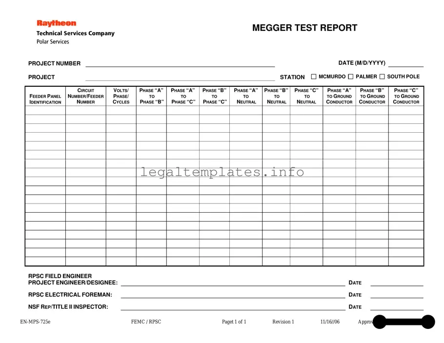
Maintaining the integrity of electrical installations is crucial in avoiding system failures that can lead to significant downtime and safety hazards. One key tool in this preventative maintenance process is the Megger Test report form, an essential document designed to record the insulation resistance measurements of electrical circuits and equipment. This form meticulously captures details ranging from project numbers and station locations, including McMurdo, Palmer, and South Pole, to specific data points such as feeder panel identification, circuit numbers, and voltage measurements across various connections (Phase “A” to “B”, “A” to “C”, “B” to “C”, and each phase to neutral and ground conductors). Furthermore, it documents the identities of key personnel involved in the testing process, including the RPSC field engineer, project engineer/designee, electrical foreman, and the NSF representative or Title II inspector, ensuring a comprehensive audit trail. The form, identified as EN-MPS-725e FEMC / RPSC and last revised on 11/16/06 with approval from Wayne L. Cornell, serves as a critical checkpoint in ensuring the electrical infrastructure's reliability and safety at crucial research stations.
MEGGER TEST REPORT
PROJECT NUMBER
PROJECT |
|
STATION |
DATE (M/D/YYYY)
MCMURDO 
 PALMER
 SOUTH POLE
FEEDER PANEL IDENTIFICATION
CIRCUIT
NUMBER/FEEDER
NUMBER
VOLTS/
PHASE/
CYCLES
PHASE “A”
TO
PHASE “B”
PHASE “A”
TO
PHASE “C”
PHASE “B”
TO
PHASE “C”
PHASE “A”
TO
NEUTRAL
PHASE “B”
TO
NEUTRAL
PHASE “C”
TO
NEUTRAL
PHASE “A”
TO GROUND CONDUCTOR
PHASE “B”
TO GROUND CONDUCTOR
PHASE “C”
TO GROUND CONDUCTOR
RPSC FIELD ENGINEER |
|
|
|
|
|
|
PROJECT ENGINEER/DESIGNEE: |
|
|
|
|
DATE |
|
RPSC ELECTRICAL FOREMAN: |
|
|
|
|
DATE |
|
NSF REP/TITLE II INSPECTOR: |
|
|
|
|
DATE |
|
FEMC / RPSC |
Paget 1 of 1 |
Revision 1 |
11/16//06 |
Approved by Wayne L. Cornell |
||
| Fact Name | Description |
|---|---|
| Purpose of the Form | This form is used to record the results of a Megger Test, which measures the insulation resistance of electrical wiring and equipment to ensure they are operating safely and efficiently. |
| Key Components | Includes details such as project number, station, date, feeder panel identification, circuit number, feeder number, voltage, phase, cycles, and resistance measurements between different phases and grounds. |
| Applicable Locations | Designed specifically for use in McMurdo, Palmer, and South Pole stations, indicating its suitability for extreme and varied conditions. |
| Approval and Revision | The form was approved by Wayne L. Cornell on 11/16/06 and is identified as revision 1, highlighting its official use and updating protocol. |
| Governing Bodies Involved | Includes signatures from RPSC Field Engineer, Project Engineer/Designee, RPSC Electrical Foreman, and NSF Rep/Title II Inspector, indicating a comprehensive review and approval process. |
Completing a Megger Test form is a straightforward process that ensures electrical installations at specific sites meet safety and quality standards. The form collects data on the insulation resistance of electrical circuits, helping to identify any potential issues that could compromise safety or efficiency. Once the form is filled out, it serves as a formal record of the test conducted, vital for future maintenance, inspections, or audits. Here’s how to accurately complete a Megger Test form.
Once you’ve filled in all the required information on the Megger Test form, review it for accuracy. This document is crucial for maintaining project integrity and ensuring compliance with safety standards. It’s also important for traceability, should any issues arise in the future. Keep this form with the project’s other essential documents for easy reference.
What is a Megger Test Report?
A Megger Test Report is a document that records the insulation resistance measurements of electrical circuits. It's used to ensure the safety and functionality of electrical installations, typically within construction projects or existing electrical infrastructure. The report includes details like the project number, station, date, and specific electrical measurements such as resistance between different phases and to ground.
Why is the Megger Test important?
The Megger Test is crucial for identifying potential electrical hazards before they lead to failure or accidents. By measuring insulation resistance, engineers can determine if the insulation is performing as expected or if it has deteriorated. This is essential for the maintenance of electrical systems, helping prevent short circuits or electrical fires.
What information is included in the Megger Test Report?
The report contains significant details, such as the project number, station (e.g., McMurdo, Palmer, South Pole), and the date of the test. It also includes identification numbers for feeder panels and circuits, volts/phase/cycles, and resistance measurements between various phases and from phases to neutral and ground. Additionally, it lists the names and titles of the responsible engineers and inspectors.
How is the resistance measurement indicated in the report?
Resistance measurements are presented in ohms and they reflect the quality of insulation between electrical conductors. The report outlines these values for different configurations: phase “A” to phase “B”, phase “A” to phase “C”, phase “B” to phase “C”, and each phase to neutral and ground. Lower resistance values suggest compromised insulation which could lead to safety hazards.
Who approves the Megger Test Report?
The final approval for the Megger Test Report is given by an authority within the issuing organization, in this case, Wayne L. Cornell as noted in the document. It's also reviewed and signed by project engineers, the electrical foreman, and representatives from the National Science Foundation (NSF) or Title II inspectors, ensuring comprehensive oversight.
When should a Megger Test be conducted?
Megger Tests are typically conducted in two instances: before putting a new electrical installation into service (to ensure it is safe and meets all required standards) and as part of regular maintenance of existing systems (to catch and rectify deterioration of insulation before it leads to failure).
What does a low insulation resistance value indicate?
A low insulation resistance value suggests that the insulation of the electrical system might be compromised, allowing current to leak through unintended paths. This poses a risk of short circuits, equipment failure, or even fire hazards, indicating an urgent need for repair or replacement of the affected components.
Can anyone conduct a Megger Test?
Conducting a Megger Test requires specialized knowledge and equipment. It is typically performed by qualified electrical engineers or technicians who have been trained to use a Megger or insulation tester safely and interpret the results accurately. This ensures that the testing process itself does not introduce additional risks to the system or personnel.
What do the different test locations like McMurdo, Palmer, and South Pole signify?
In this specific context, these locations likely refer to different stations or sites managed by the Polar Program, where the electrical installations are being tested. Such distinctions help in organizing and tracking the safety and compliance of electrical systems across diverse and remote locations.
How is the Megger Test Report used by electrical foremen and engineers?
Electrical foremen and project engineers use the Megger Test Report to verify the condition of the electrical insulation and to make informed decisions about necessary repairs or replacements. It serves as a critical tool in ensuring the electrical safety and compliance of installations, guiding maintenance schedules, and identifying potential risks in the system's design or installation.
Filling out the Megger Test report requires attention to detail and a clear understanding of the form structure and content. A common mistake is incorrect or incomplete project information. The form necessitates specific details such as the project number, station, and the date in the format M/D/YYYY. Often individuals might overlook the importance of accurately filling in this section, leading to confusion or misplacement of reports. Entering the correct project information is crucial for the report's identification and future reference.
Another prevalent error occurs in the feeder panel identification section. This area is vital for discerning the specific electrical circuit being tested. It is not uncommon for individuals to mistakenly input the circuit number or feeder number without verifying its accuracy. Such inaccuracies can lead to significant confusion, potentially resulting in a misdiagnosis of electrical issues.
When it comes to the measurements sections, such as volts, phase, and cycles, as well as the insulation resistance measurements between phases and to ground, precision is paramount. Nonetheless, inaccuracies frequently arise from hastily recorded measurements or misunderstanding the measuring units. This is problematic because these figures are essential for assessing the electrical insulation's condition. Incorrect data can lead to improper maintenance decisions.
Misinterpretation of the phases is yet another mistake. The form requires specific insulation resistance measurements between different phases and their connection to neutral and ground. Mislabeling or confusing these connections, such as misidentifying phase “A” for phase “B” and so on, can skew the test results, concealing potential hazards.
The role and name of individuals involved in the test are also critical components. The form demands the names and dates for the RPSC field engineer, project engineer/designee, RPSC electrical foreman, and NSF rep/title II inspector. Often, individuals either leave these sections blank or input incomplete information. Ensuring that these details are accurately filled can safeguard against accountability issues and facilitate clear communication channels.
Failure to pay attention to the document's version and approval details, such as the revision number and the approval date, represents another oversight. The form EN-MPS-725e FEMC/RPSC page 1 of 1 Revision 1, approved by Wayne L. Cornell on 11/16/06, is periodically updated. Using an outdated form can lead to non-compliance with the current testing standards and procedures.
Errors in the selection of the project station, choosing between McMurdo, Palmer, and South Pole, are not uncommon. This choice is pivotal as it helps in organizing and accessing the reports based on their geographical relevance. A wrong selection might route the report to the incorrect department or team, delaying the maintenance process.
Last but not least, overlooking the date fields for the RPSC electrical foreman and the NSF rep/title II inspector is a minor yet recurrent mistake. The form stipulates that these dates be entered next to the relevant names. Leaving these dates unfilled may seem inconsequential but can lead to issues in tracking the report's progression and verifying its timely completion.
When conducting inspections or maintenance in the electrical field, professionals rely on various forms and documents to ensure thoroughness and compliance with standards. One such document is the Megger Test form, a crucial tool used to measure insulation resistance in electrical circuits—a key indicator of the health and safety of electrical installations. However, this form is often just one piece of a larger puzzle. Several other documents are typically used alongside it to paint a full picture of an electrical system's condition and compliance.
Collectively, these documents form a comprehensive toolkit for ensuring the safe and efficient operation of electrical systems. Workers in the field use them to document conditions, maintenance needs, and compliance with safety standards, thereby playing a critical role in preventing accidents and ensuring the longevity of electrical installations. The Megger Test form, with its focus on insulation resistance, is a vital part of this ecosystem, providing a snapshot of an electrical system's insulation health and contributing to a broader understanding of its overall condition.
The Megger Test Report shares similarities with an Electrical Inspection Report, primarily in its function of recording assessments of electrical systems. Both documents catalog essential information about electrical circuits, including voltage and grounding integrity. They serve to ensure that electrical installations meet safety and compliance standards, reporting on the condition and performance of the system inspected. The key difference lies in the scope, with the Megger Test Report focusing specifically on insulation resistance measurements.
Another document closely related to the Megger Test Report is the Equipment Maintenance Log. This log tracks the condition, repairs, and general maintenance of electrical equipment over time. Both documents contain critical data about the operational state of electrical components, yet the Megger Test Report is more focused on the insulation status, whereas the Maintenance Log encompasses a broader range of equipment care, including repairs and routine checks.
Project Documentation or Project Status Reports are also similar to the Megger Test Report in that they outline specific details and progress within a project. These reports could include data on electrical testing as part of the larger project scope, providing stakeholders with updates on various aspects of the project’s progress, including compliance with electrical standards. However, the Megger Test Report is more technical and targeted, especially concerning electrical safety and integrity.
The Commissioning Report, which is created at the completion of a project, often includes results from various tests, including those similar to the Megger Test, to verify that all systems are operational and meet the project specifications and standards. It serves as a final check, incorporating many types of test results, of which the Megger Test could be a part. This report confirms that all aspects of the project, including the electrical installations, are complete and in compliance with the design.
A Risk Assessment document, essential for identifying potential hazards associated with electrical installations and creating mitigation strategies, also echoes aspects of the Megger Test Report. While assessing insulation resistance as part of the Megger Test contributes to minimizing electrical risks, the broader Risk Assessment identifies various hazards and proposes preventive measures. The connection here lies in the focus on safety and the prevention of equipment failure or accidents.
The Quality Control Checklist is another document that parallels the Megger Test Report, as it ensures that specific standards and criteria are met before, during, and after installation of electrical systems. Such checklists often include items similar to those found in a Megger Test, ensuring that every aspect of the installation adheres to high-quality standards and complies with local and national codes. The Megger Test Report is a more focused form of quality control, specifically looking at electrical insulation integrity.
Finally, the Warranty Document, which guarantees the condition and functionality of electrical installations for a specified period, bears resemblance to the Megger Test Report. Ensuring that electrical systems are tested for insulation resistance can be crucial for the validity of a warranty, as it verifies the initial and ongoing compliance and quality of the electrical work completed. While the Warranty Document serves as a promise of performance and remedy, the Megger Test Report provides the technical evidence needed to uphold the warranty's terms.
When filling out the Megger Test form, attention to detail is crucial for ensuring the accuracy and reliability of the data. Below is a compilation of essential dos and don'ts to guide you through the process.
Do:
Don't:
Following these guidelines will help maintain the integrity of the Megger Test process, ensuring that the testing outcomes are reliable and valid. Remember, this form is a critical document that contributes to the safety and efficacy of the project's electrical systems.
Common misconceptions about the Megger Test form can lead to confusion and misuse of the document. It is crucial to understand the form correctly to ensure electrical safety and compliance. Here are eight misconceptions explained:
By clarifying these misconceptions, individuals can use the Megger Test form more effectively, ensuring electrical systems are safe, well-maintained, and compliant with relevant standards.
When it comes to ensuring the safety and efficiency of electrical installations, the Megger Test plays a crucial role. This test measures electrical insulation resistance, which is vital in preventing accidents and ensuring the longevity of electrical systems. Below are five key takeaways about filling out and using the Megger Test form effectively.
Utilizing the Megger Test form correctly is not just about following procedures; it’s about ensuring the safety, efficiency, and longevity of electrical installations. By focusing on accuracy, comprehensiveness, proper authorization, documentation, and approved protocols, individuals can contribute to safer electrical environments across any project.
Is Medicare Based on Income - Effectively utilizing this form can alleviate the burden of increased Medicare costs during times of financial transition.
Fed Ex Frieght - Provides an official record of the agreement between the shipper and FedEx regarding transportation terms.